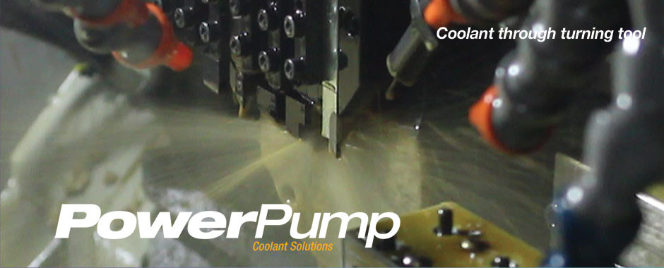
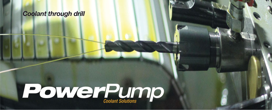
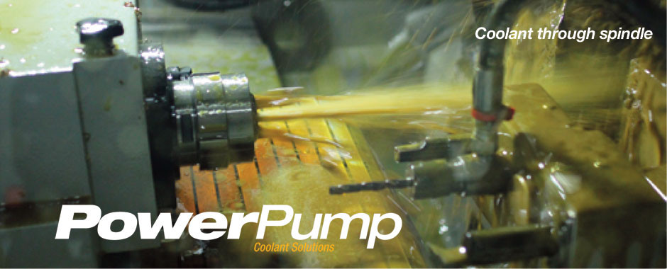
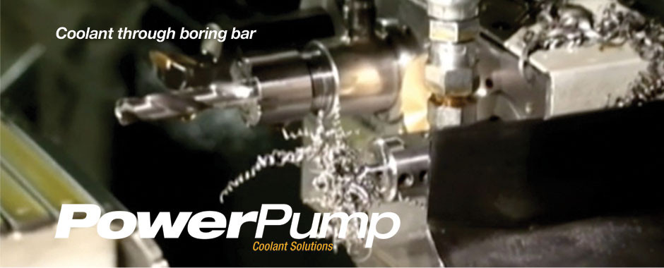
Directing the coolant to a precise location at the correct pressure and flow rate will maximize coolant effectiveness. Laminar flow over the cutting tool’s top edge and the underside of the generated chip will eliminate the semi conductive vapor barrier created by the boiling coolant. This will also break the chips into smaller removable pieces.
When fluid passes from a larger diameter to a smaller diameter in a tube, the flow rate requirements are less to achieve a higher velocity output, inversely the larger the orifice the greater the flow rate requirement to maintain the desired pressure.
Proven scientific formulas and theories for high-pressure coolant provide the following data:
- Each horsepower used to drive a cutting tool requires .5GPM of coolant.
- Drills require 10 GPM per inch of drill diameter.
- The tool/chip interface can reach temperatures up to 750°C.
- Laminar flow over the cutting tool’s top edge and the underside of the chip will eliminate the semi conductive vapor barrier created by boiling coolant this will also break the chip into smaller removable pieces.
- Excessive tool wear is caused by the cutting tool absorbing the generated heat by longer tool/chip contact and re-cutting of generated chips.
Knowing this, the high-pressure cooling parameters can be strategically tuned.
High pressure coolant is not the only consideration. The flow rate and orifice size must also taken into account. The Bernoulli theory expresses the relationship between pressure, velocity and the flow rate. As fluid passes from a large diameter to a smaller diameter in a tube the flow rate requirements are les to achieve a higher velocity output, inversely the larger the orifice the greater the flow rate requirement to maintain the desired pressure.
The calculator will provide the necessary pressure settings to produce the required volume of coolant for each cutting tool based on horsepower and orifice diameter.
Example:
Turning tool consumes 5.0 HP and has 3 orifices at .035” diameter.
5.0 HP requires (.5GPM/HP x 5.0 HP)= 2.5 GPM.
Three orifices at 810 PSI= 2.5GPM
Thermal changes in the machine tool are generated by the change in coolant temperature.
When a high-pressure coolant system generates more coolant flow than is required by the specific tool receiving the coolant, the excess coolant must be diverted across a pressure relief valve. This generates heat that is absorbed by the coolant and then transferred to the machine components, adversely affecting machine repeatability.
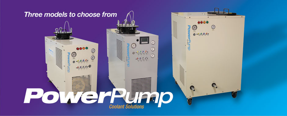
The solution is the infinitely adjustable pressure by output port which is an option on the POWERPUMP. All the coolant flow goes directly to the designated tool at the pressure selected and no flow is diverted across a relief valve, eliminating thermal instability.

